BASE FRAME
 [10/18/2004]
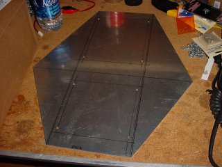
I didn't get as much done tonight as I had hoped. No surprise there. However, I now have
a base plate cut out. I also drilled and chamfered some holes for some bolts to mount up
the frame sides, but I didn't have time to actually drill any corresponding holes in the
frame pieces. I'll do that on Wednesday...or perhaps at home in the interim. I spent a lot
of time trying to peel off the protective backing from the plate - apparently, the metal is
old and the backing was brittle, so it took quite an effort to get it all off.
I weighed all the parts and computed the estimated weight of the remaining and arrived at a
total weight of 12.63 pounds. Unfortunately, this does not include the weapon. It includes
the drive motor for the weapon, but does not include the motor controller, the drive train
and associated hardware, or the spinning disc. This is bad news, since the total target
weight for its weight class needs to be 12 lbs. I didn't compute the weight of the weapon,
but I'm sure I'm looking at about 15 lbs in the end. NOT good!
 [10/20/2004]
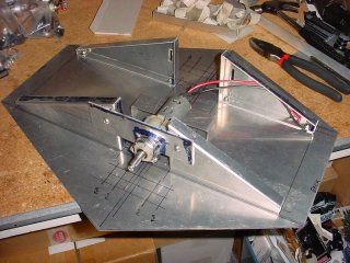
I drilled holes in the four base frame pieces and bolted them down to the base plate. Everything appears to be right on the line, and everything is right in tolerance. Not bad for using some basic hand tools to do the job! Good measurements help, too. I even got one of the motors mounted in this shot. As you can see, I still need to mill some slots in the base place to allow the wheel to descend through it. As you can see, I have it all marked out, ready to cut. I'll just have to disassemble everything in order to cut it.
 I mounted up the other motor so that both motors were mounted to the base frame. The gap
between the two motors was almost precisely what I designed it to be (although the spacing
was arbitrarily chosen), which was 1/16-inch. It's a tiny bit wider than that, but the
frame sides are not 100% square. When the frame sides are pulled in square (where they will
be when I attach the battery tray), the gap shrinks right down to 1/16-inch!
I mounted up the other motor so that both motors were mounted to the base frame. The gap
between the two motors was almost precisely what I designed it to be (although the spacing
was arbitrarily chosen), which was 1/16-inch. It's a tiny bit wider than that, but the
frame sides are not 100% square. When the frame sides are pulled in square (where they will
be when I attach the battery tray), the gap shrinks right down to 1/16-inch!As you can see, the motors are slightly offset. This was to allow for a narrower profile (to save weight) and has been proven in other robots to not upset driving characteristics. However, had I computed the weight earlier, I would have made it even narrower, since the robot is currently overweight. But this would have required a re-design to allow the motors to sit next to each other.
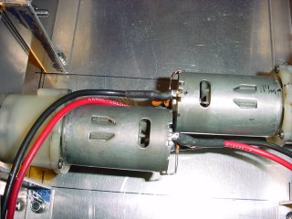
 Here is a close-up view (well, closer, anyway) of the motor mounting flange. I basically
just took a piece of metal and milled a 1/4" slot in it (you can kind of see it across
the top of the gearbox), then used some shears to make an angled cut to separate the
lower flanges, then used a press brake to fold the flanges out. The gearbox on the motor
has two flat sides, so it slides up in between the flanges, then I just wrap a hose clamp
around that and tighten it down. Holds fairly well, but I am thinking of adding a couple
small set screws just to make sure it can't slip. I will also cut the flanges to their
final shape, tonight, since their corners protrude above the frame when adjusted to their
maximum height. A couple pictures back, you can see the slots in the frame sides that
allow the wheel height to be adjusted.
Here is a close-up view (well, closer, anyway) of the motor mounting flange. I basically
just took a piece of metal and milled a 1/4" slot in it (you can kind of see it across
the top of the gearbox), then used some shears to make an angled cut to separate the
lower flanges, then used a press brake to fold the flanges out. The gearbox on the motor
has two flat sides, so it slides up in between the flanges, then I just wrap a hose clamp
around that and tighten it down. Holds fairly well, but I am thinking of adding a couple
small set screws just to make sure it can't slip. I will also cut the flanges to their
final shape, tonight, since their corners protrude above the frame when adjusted to their
maximum height. A couple pictures back, you can see the slots in the frame sides that
allow the wheel height to be adjusted.
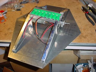 And here is how it will look when I get the battery tray attached. It is not really
attached in this picture. But it will be tonight!
And here is how it will look when I get the battery tray attached. It is not really
attached in this picture. But it will be tonight!